In this article extract, Dr Bill Eccles from Bolt Science explains what a clevis joint is and how to use Bolt Science’s BOLTCALC software for a clevis joint analysis.
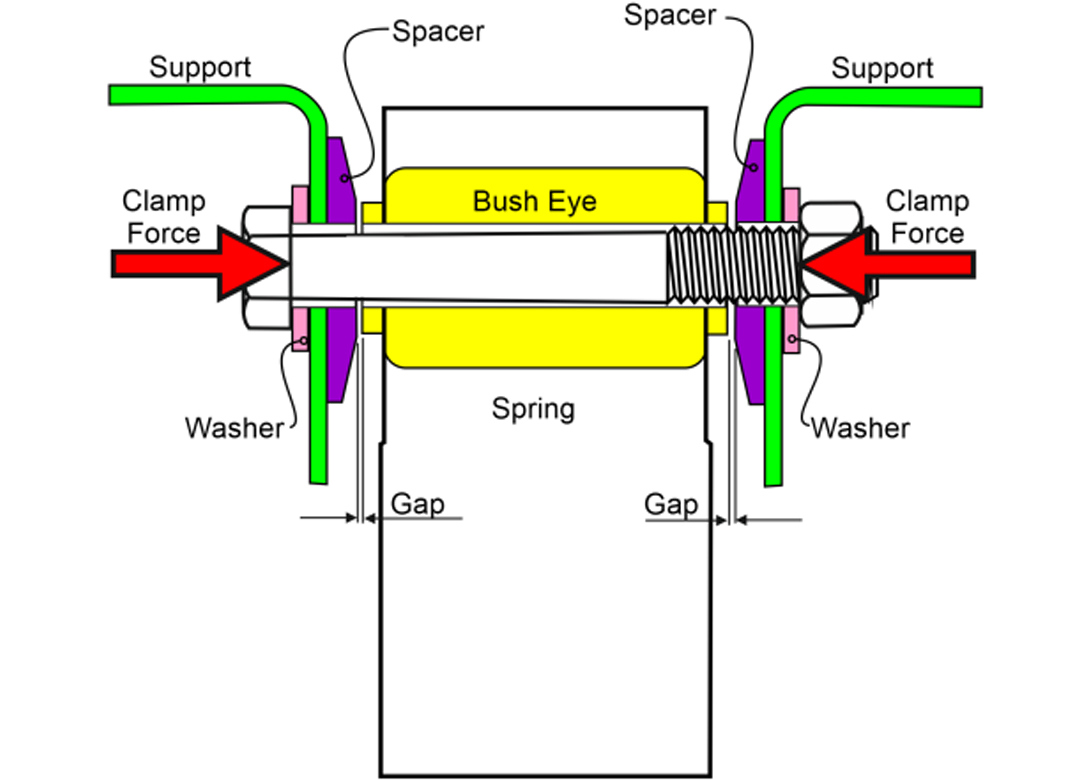
A clevis type joint consists usually of two parts, a rod or member that is trapped between two supports. Such joints are used to transmit primarily shear loads. There are a wide range of uses of such joints, the one shown in the image consists of a spring on a vehicle suspension being secured between two supports.
There must initially be a gap between the bush in the spring and the supports to allow it to be installed. The gap is closed by tightening the through bolt so that there is metal to metal contact through the joint. Accordingly, the gap is usually small so that the force needed to pull the plates together is achievable and that the supports are not over-stressed by the clamp load from the tightening process.
The advantage of clamping the parts together is that the loading from the spring is transmitted by friction grip rather than by placing the bolt into direct shear. This allows dynamic loads to be transmitted without joint slip or movement occurring. If the direct shear approach is used, the shear load is carried into the supports by a shear stress carried in the bolt. In such circumstances, the hole clearance needs to be minimised and the thread not to be in the shear plane, ideally. Clevis joints in direct shear are extensively used for applications in which the loading is not highly dynamic and having little or no requirement to transmit any side loading.
Fatigue failure of an M8 bolt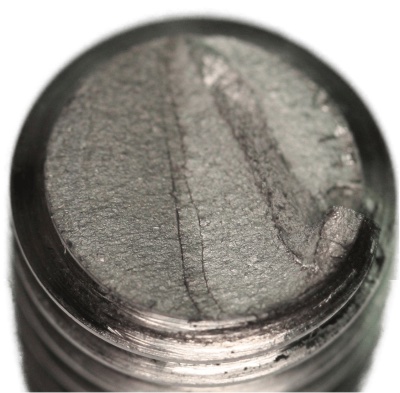
The joint that under study transmits the load using friction grip. That is, the force provided when the bolt is tightened clamps the parts together so that frictional resistance is used to carry any shear load between the connected parts. As such, the bolts do not sustain any shear force. In this application, bolts had been found to fail by fatigue, an example of which is pictured.
Such failures are often indicative of the friction grip failing. When this occurs, the joint parts will slide slightly so that the bolt then must withstand loading that it is not designed to sustain. The joint analysis performed here looks at the likely cause of the failure and how it may be fixed.
Double shear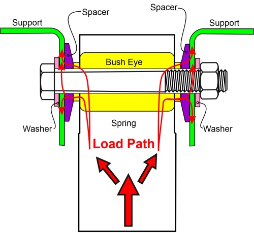
The joint pictured is in what is called double shear. That is, the force splits so that there are two shear planes. If the stiffness of each support is the same, each side will sustain half the loading. This is often not the case, and one support may be stiffer than the other. In such circumstances, the stiffer side will carry more of the loading. This can be determined by an analysis such as FEA (Finite Element Analysis). What some experienced Engineers do is to give some allowance for this effect by dividing the loading on each side by a factor less than 2, such as 1.8, to allow for such effects.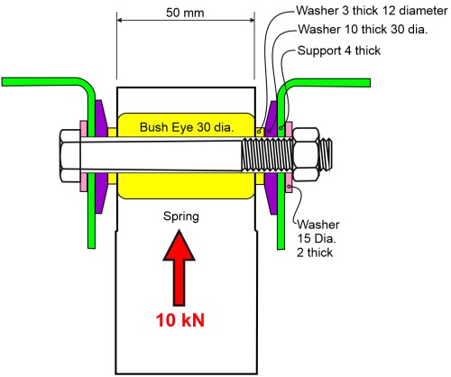
The joint consists of an M8 property Class 8.8 bolt with a property Class 8 nut. The 10kN loading is based upon the maximum dynamic loading that is likely to be encountered. The loading is fully reversible. There are other load cases, but this is deemed to be the worst case for the bolt to be able to sustain. The dimensions of the assembly are shown below.
Click here to read the full article:
www.boltscience.com/pages/BOLTCALC_Clevis_JointAnalysis.htm


Having spent a decade in the fastener industry experiencing every facet – from steel mills, fastener manufacturers, wholesalers, distributors, as well as machinery builders and plating + coating companies, Claire has developed an in-depth knowledge of all things fasteners.
Alongside visiting numerous companies, exhibitions and conferences around the world, Claire has also interviewed high profile figures – focusing on key topics impacting the sector and making sure readers stay up to date with the latest developments within the industry.

