
By Jim Parsons, fastener test engineer, j-parsons@hotmail.co.uk
Up until June 2018 I worked for a global OEM in vehicle testing, specifically carrying out ultrasonic clamp load measurement in threaded joints in regard to suspension systems and component durability testing, as well as prototype and product build tests. Here I will focus on the benefits of ultrasonic clamp load measurement.
To do this I will give a brief overview of the various processes involved in arriving at a satisfactory result, as well as look at the measurement process, fastener preparation, calibration and how the measurements are used in a test application.
Plus, I will look at tightening techniques, which will hopefully clear up any queries that arise, before focusing on examples that highlight the versatility of ultrasonic clamp load measurement.
What is clamp load?
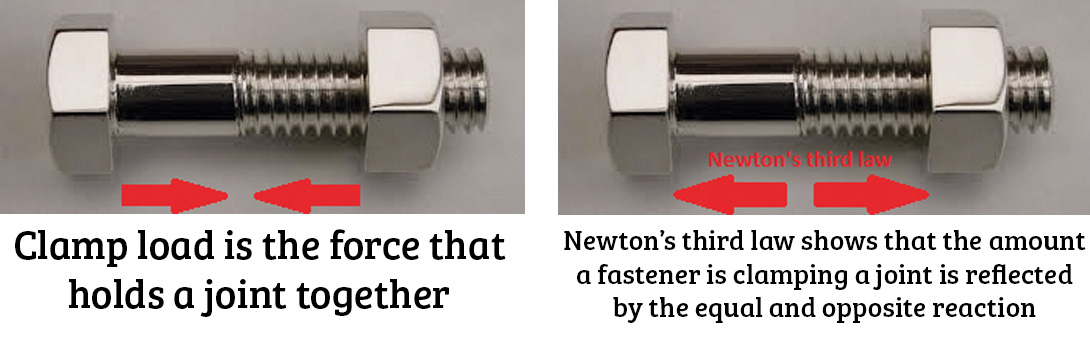
First of all clamp load should not to be confused with torque, as I’ll explain later. Clamp load is the parameter that determines the function of a threaded joint. It is, literally, the force that is holding the joint together.
It is possible to measure clamp load by inserting a load measuring washer into the application but this is necessarily a modification of the joint. Unless, of course, your application contains a load washer.
Thanks to Newton’s third law we know that the amount by which a fastener is clamping the joint is reflected by the equal and opposite reaction extending the fastener over the portion doing the work. In the last 20 – 30 years people have become acquainted with the idea of ‘stretch-bolts’, largely with regard to cylinder head fasteners, but obviously all bolts have always stretched.
Using an ultrasonic pulse, it’s this change in length that is measured to determine the installed clamp load. Whilst it is possible to also measure this with strain gauges, this can create its own problems with accessibility and wiring paths.
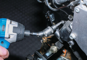
For a fairly standard suspension system assembly the test components would be assembled and fasteners tightened to specification whereupon they are ‘paintmarked’. This ‘paintmark’ serves as a visual indicator that the fastener is still ‘tight’. At the end of a test the fasteners are subject to an on-torque check at 70% of installed torque and an off-torque measurement. However, from a durability test perspective, this may be too late.
It is possible to measure the ‘on’ or ‘off’ torque at intervals during the test to ensure that it’s still ‘tight’, but this disturbs the joint and may artificially strengthen or weaken it. By using ultrasonic clamp load measurement it’s possible to monitor the actual joint without disturbing it or influencing its integrity, which is ideal for this scenario.
Historically, ultrasonic clamp load measurement in my particular world came about as a result of durability failures of fasteners with organic zinc flake and similar coatings. During suspension rig testing, fasteners were believed to have come ‘loose’ even though the ‘paintmarks’ were still aligned. In some cases it was found that the thicker coating had allowed slight movement within some joints, eroding the coating, resulting in reduced tension resistance and a corresponding drop-off in clamp load.
Ultrasonic clamp load measurement has since become an integral part of durability testing as both a diagnostic and verification tool. In addition to which, in a number of cases it has been used to refine or even define tightening strategies for prototype build and production.
Measurement process overview
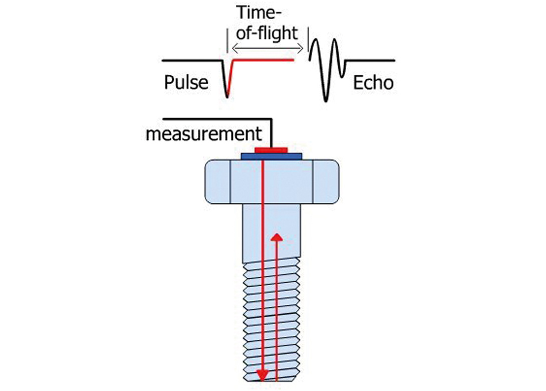
The ultrasonic clamp load measuring device works by means of sonic echo reflections, similar to sonar but much higher frequency. The ultrasonic generator excites a Piezoelectric amplifier attached to one end of the fastener – producing an ultrasonic pulse. This travels the length of the fastener and is reflected back. The reflection echo is processed by the unit and displayed on the view screen. The length of the fastener is measured in terms of the Time of Flight (TOF) between the original Pulse and the Echo reflection.
Using the differences in TOF between the loose and tightened states of the fastener, the measuring device calculates the change in length of the fastener and therefore the load it is applying to the joint.
Fastener preparation
The ends of each fastener must be machined to provide two parallel surfaces of good surface finish to ensure effective transmittal and reflection of the ultrasonic pulse. By way of example, a standard hex head bolt is typically surface ground at each end. This is done by clamping a number of fasteners in a two part fixture that is capable of flipping 180°, to grind each end, without disturbing the fasteners.
The end surfaces are then cleaned and degreased before a Piezoelectric sensor is glued to the centre of one end (usually the head) using a suitable adhesive.
Calibration
In an ideal world every fastener to be fitted would have its own unique calibration, as each can have a slightly different internal structure even if they are made to the same specification. However, calibration requires the fastener to be tightened and this may affect how it subsequently behaves in the actual joint. For example, by removing any coating it may have and therefore effecting a dimensional change. I have also seen that the load/relax cycle can have the effect of physically ‘annealing’ the fastener.
In any case, for very large numbers this would obviously take a considerable amount of time so it is my practice to calibrate fasteners in batches. If only three fasteners are required for each of six tests and all the joints are the same, I may request 24 and machine, instrument and calibrate all of them as one batch. If 240 cylinder head bolts are required for 20 – 30 tests I may, for example, split these into batches of 80.
Calibration can be split into three parts:
- Echo analysis.
- Temperature calibration.
- Load calibration.
Echo analysis
First, I would generate a signal that contains all of the features that I require for repeatable measurement across the entire batch of fasteners and set the measurement window to the portion of the time axis at which the ultrasonic pulse will echo back. Once the necessary adjustments are made to the window parameters, I’d achieve a clear crisp echo peak (circled in Figure 1).
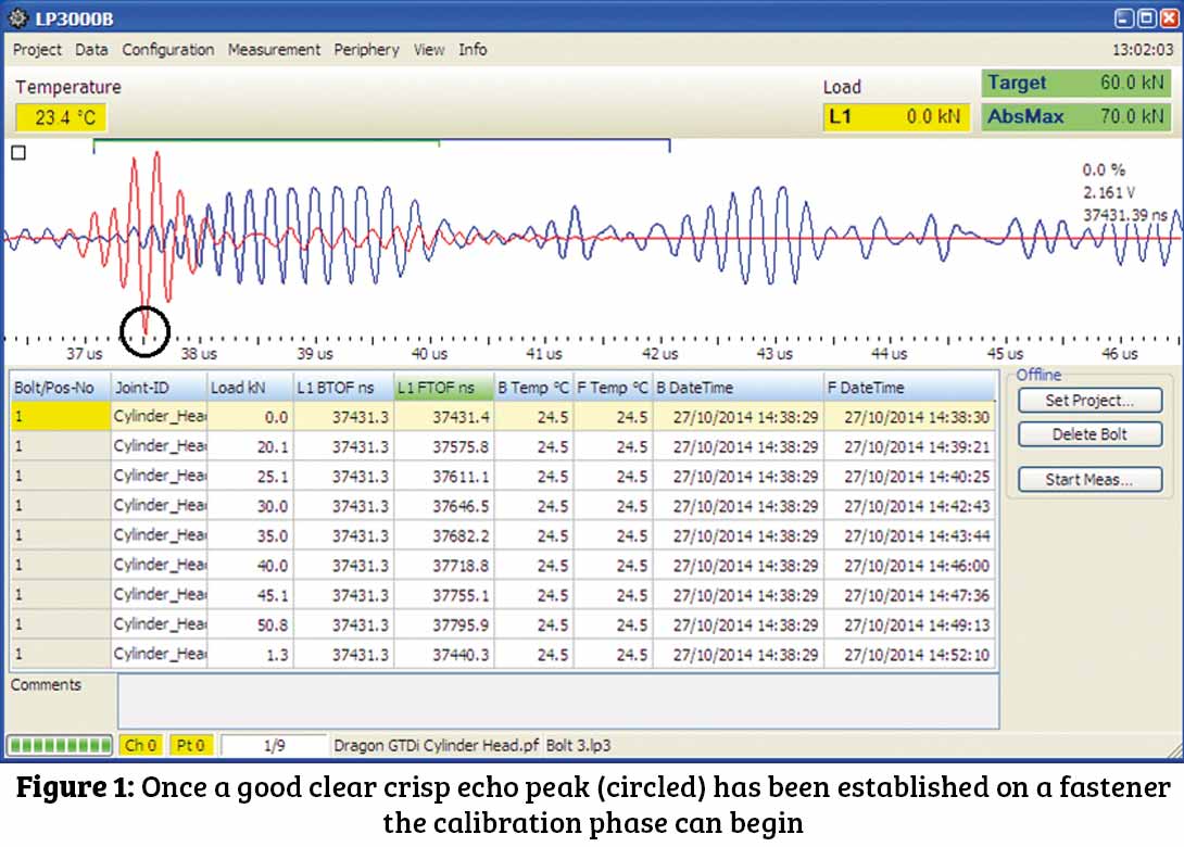
This peak will be used every time a measurement is taken and indistinct signals can result in distortion where the datum peak recedes upwards and another (either side) succeeds it. This leads to incorrect measurements as the unit measures to/from the wrong peak and therefore an erroneous TOF. Once a good clear crisp echo peak has been established on all of the fasteners then the calibration phase can begin.
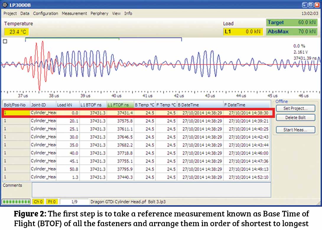
To start, I would take a reference measurement known as a Base Time OF Flight (BTOF) of all fasteners and arrange them in order of shortest to longest (Figure 2).
Temperature calibration
For temperature calibration I would take a fastener from the middle of the BTOF range and measure the TOF as it is taken from -20°C to 80°C, holding the temperature for 90 mins at each 10°C step. A Scale Factor is then calculated to negate any changes in reading due to temperature. This is only really required if there are likely to be large temperature differences between measurement intervals, but I would normally leave this running overnight so it really doesn’t take much more time to do as a matter of course.
Load calibration
Before any load calibration is carried out certain critical information about the joint is required such as target load (kN), tightening specification and joint length.
Joint length is the portion of the fastener that is actually doing the work. Also known as grip length, especially in North America, it refers to the clamped portion of the joint (e.g between the engaged threads and the surface onto which the tension is applied).
I would tend to refer to the tightening specification as a loose sanity check. Loose because I would use grease to lubricate the whole assembly and preserve the life of my adaptors and spacers and therefore have to make an adjustment to the torque measurement to account for the reduced friction.
A dedicated calibration bench is required with a selection of load cells mounted to it – suitable to cover all expected clamp loads. For example, I had 0kN – 20kN, 0kN – 50kN, 0kN – 100kN and 0kN – 250kN load cells available to be fitted to the bench to cover a good range of loads.
Using an adaptor with a female thread and spacers (essentially large washers) the exact joint length is replicated. Thus, when the fastener is tightened and compresses the load cell, it is stretched over the same portion as it is in the actual application. This is essential to ensure consistency between calibration and test measurements. The fastener is tightened in increments up to the target range as shown on the load cell display.
Again, to average out the batch I’d tighten the longest and shortest fasteners, by BTOF, and calculate the scale factor required to equate the U/S device measurement with that of the load cell. This is then ‘proven’ with one or two fasteners from the middle of the BTOF range using this calculated scale factor.
In doing this, the measurement equipment is effectively tuned to the application. The results of this are recorded in a calibration certificate and issued to the requestor. This would show the comparison between load cell and ultrasonic measurements and the error between them. It also states the calibration scale factor used, as well as part numbers and critical joint information.
Again, this may only be valid for the current batch of fasteners so calibration checks could be required of further batches if more testing is required.
Application
After all of this, the ‘test’ portion of the measurement is fairly straightforward. I would attend the application to supply the instrumented fasteners and carry out the installation measurements. This may be, for example, a suspension system rig with a full set of instrumented fasteners, a component test rig, prototype engine build or a simple bench test.
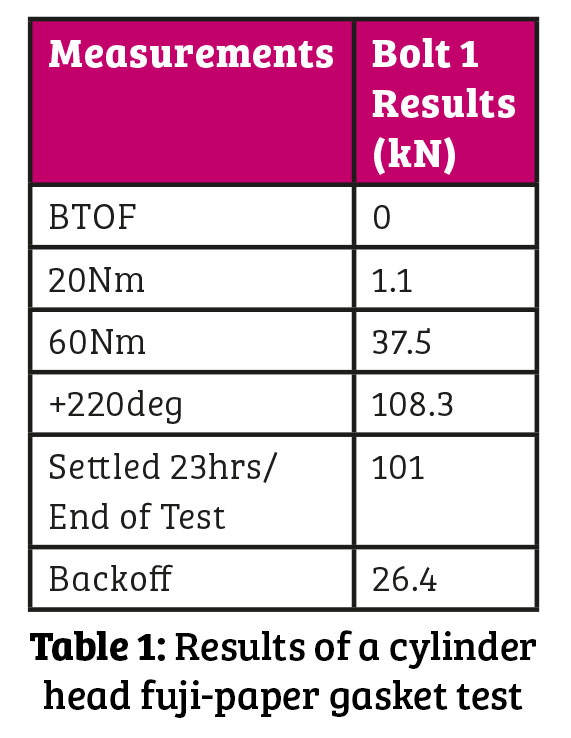
In Table 1 we can see the results for a cylinder head fuji-paper gasket test. If we focus on the readings for Bolt 1 we can see that our measurements will consist of a BTOF to establish our benchmark, followed by readings at each stage of the tightening process; 20Nm, 60Nm, +220°C and a settled measurement, ideally taken after 24 hours. In this case, the settled measurement represents our end of test reading before we loosen the fasteners. In the case of durability or dyno testing, there may also be periodic measurements during the test to determine any gradual loss of clamp load due to heat and/or load cycling.
You may have noticed that the back off (loosened) measurement doesn’t represent a return to 0kN clamp load and I’ll explain why, later. But first…
Tightening technique
Currently, for non-critical fastenings, a torque specification is used to establish the integrity of the assembled joint. However, torque is merely a measurement of how much effort is required to turn the fastener and is therefore largely an expression of the friction within the joint.
That is, friction between the mating threads and clamping surfaces This can lead to a large variation in resultant, installed, clamp load for a given torque. Where friction is variable, there can be a dramatic disparity in clamp load installed for a given torque.
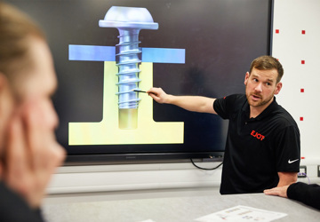
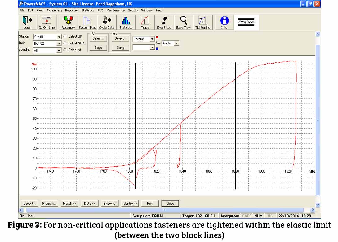
Normally, for non-critical applications, these fasteners are tightened within their elastic limit (Figure 3) and can be reused. As such, the extension of the fastener is directly proportional to the clamp load installed.
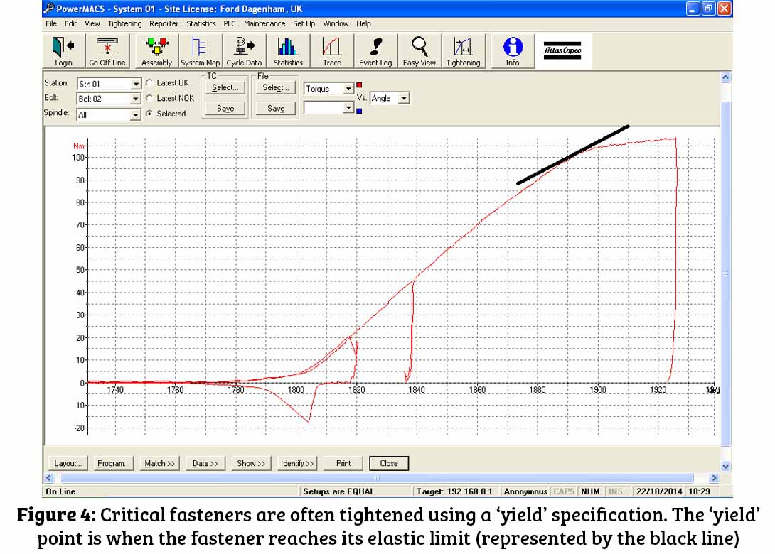
Critical fastenings are often tightened using a ‘yield’ specification whereby the torque is monitored with respect to the angle through which the fastener is turned. The ‘yield’ point is the point at which the fastener reaches its elastic limit, the point at which the fastener can apply the maximum tensile load and still be reused (Figure 4). Beyond this point the torque/angle curve gradient reduces as the fastener permanently deforms. As such these fasteners may only be reused a few times, if at all.
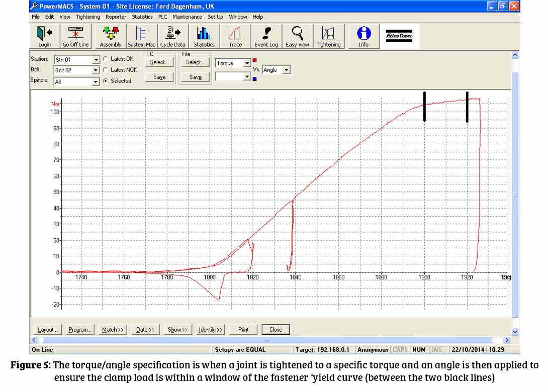
Somewhere between these two is the torque/angle specification whereby a joint is tightened to a specific torque and an angle is then applied to ensure that the clamp load is within a window of the fastener ‘yield’ curve (Figure 5).
To refer back to our Back off reading from the cylinder head bolt test (Table 1). If a fastener is yielded (i.e. taken beyond its elastic limit) our measurement will consist of the actual, installed, clamp load plus the permanent, plastic, deformation.
In order to calculate the actual, installed, clamp load I would subtract this positive offset from the original measured value. Again if we focus on Table 1, we see that the settled measurement is 101kN, the ‘back off’ is 26.4kN and therefore the actual, installed, clamp load at settled is 74.6kN. The reason I do this is because I would only calibrate for the linear portion of the U/S Device/Load Cell graph (i.e. within the elastic range) using a first order polynomial equation (y=mx).
As such, the measurement you see in the plastic deformation (yield) range is a description of what the load would be if the deformation were still elastic and the loading linear. Similarly, the ‘back off’ measurement is a description of what the permanent extension would represent in terms of linear, elastic loading. Subtracting the latter from the former equals out and negates any error in these measurements.
It is possible to calibrate for yield measurements, but it requires more fasteners, more increments and much greater care to ensure accurate calculation of a second order polynomial scale factor to describe the gradient of the curve.
Ultimately, all this extra work would achieve is to remove the need to subtract the permanent extension from the settled, and any subsequent, measurement. Apart from the fact that it’s quicker and easier to carry out, I find this scenario much easier to explain to the uninitiated and it gives a very obvious indication of whether the fastener has yielded.
Versatility
I have managed to carry out measurements on fasteners from very small M6 x 15 brake hose bracket screws, tie bars, cylinder head, con rod and big end bolts, all the way up to exhaust manifold studs and driveshafts. A driveshaft being essentially a large, strangely shaped bolt onto which a hub is clamped with a hub nut. If there is a thread that is clamping something between two surfaces, and there is accessibility to either end of the threaded rod, then it’s possible to measure its extension and therefore the clamp load installed during tightening.
About the author
Jim Parsons started as an apprentice with a global automotive OEM, before developing his experience in building and installing assembly machine tools then latterly, specifically, nut runner tools and tightening systems on the production lines of various vehicle and engine manufacturers. This gives him vast experience in fasteners and tightening technology, particularly with regard to a production line environment.He then rejoined the global automotive OEM and for the last 8 years has been developing his experience in ultrasonic clamp load measurement with regard to suspension system and component durability testing, as well as prototype and production build and tests.


Will joined Fastener + Fixing Magazine in 2007 and over the last 12 years has experienced every facet of the fastener sector – interviewing key figures within the industry and visiting leading companies and exhibitions around the globe. Will manages the content strategy across all platforms and is the guardian for the high editorial standards that the brand is renowned.