
By Dr Bill Eccles, Bolt Science
A question that is sometimes asked is what tolerance should be placed on a torque value. I remember in my early days in engineering that the quality department requested that a tolerance be placed on a torque value that I had specified. I was told that without a tolerance, how were they expected to know what was acceptable to the design department?
Many organisations probably most, specify a single torque value with no tolerance. Other companies have some documentation for quality inspection may well specify a tolerance on that single value for checking purposes. Placing a tolerance on the drawing runs the risk of a person setting the torque tool to the high or low value provided. The torque value applied could then be higher or lower than the specified range due to the additional error from the tool accuracy. Without an acceptable torque range or a tolerance, problems tend to occur if a dispute arises on what is acceptable.
 Nothing in the physical world is exact, all is subject to some degree of change and measurement error. In low volume production with a familiar manufacturer, who knows the application, you may specify a dimension for a part without specifying a tolerance. This may work fine without any problems being experienced. In higher volume production, with the part being made perhaps by a manufacturer with no knowledge of the application, specifying a tolerance can prevent an assembly issue. The same, it can be argued, applies to a torque value.
I thought about the request and decided that a +/- 5% tolerance should be easily achievable. So if the nominal torque value was say 100Nm, a 95Nm to 105Nm should be very doable. Only with experience did I realise that this was not necessarily so and I had underestimated the likely scatter in the torque value that would occur under normal production conditions.
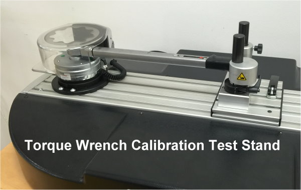
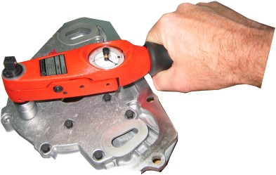
For the calibration of hand torque tools, an applicable standard is ISO 6789 ‘Assembly tools for screws and nuts, hand torque tools, requirements and test methods for design conformance testing, quality conformance testing and recalibration procedure’. This standard defines various types of torque tools. Indicating torque tools, type 1 in the standard, measures the torque means of a mechanical scale, dial or electronic display.
A setting torque tool, type 2 in the standard, is pre-set to a certain torque value and when that torque is reached some audible, visible, or other signal is given. A clicker wrench is a setting type tool and is normally the type of tool used in assembly operations. The permissible deviation from the set value depends upon the specific tool type but is either +/- 4% or +/- 6% depending upon the type of tool used.
When tested to the standard, the force needs to be applied to the torque tool within +/-10 degrees of a right angle to the longitudinal axis of the tool. Also, from 80 % to the final target torque value, the load must be applied slowly and uniformly. It is not always the case in a production environment that the tightening is completed slowly and uniformly approaching the final torque value. Nor is always the case that the person pulls the wrench at right angles to the tool axis. These factors increase the scatter in the applied torque.
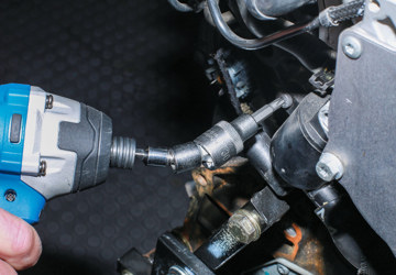
 With power tightening tools, the performance test frequently used is ISO 5393 ‘Rotary tools for threaded fasteners, performance test method’. The torque delivered by a power tool is sensitive to the joint stiffness which influences the torque rate, the torque rate being the rate of increase in the torque as the fastener is tightened. A soft joint, is one that has a low stiffness and low torque rate; a hard joint being one having a high stiffness and high torque rate. A soft joint will absorb more energy from the tool compared with a hard joint and deliver a different torque value, the difference being referred to as the mean shift and is an indication of tool performance. For power tools in which a person reacts the torque, as against fixtured tooling in which a structure reacts the torque, levels of accuracy similar to hand tools are achievable.
The torque specified, say for example 100Nm, is the value that the tightening tool should be set to. Similarly, if a torque range is specified, say 90Nm to 110Nm, the mean value, i.e. 100Nm, should be the tool value. The tolerance is largely for torque auditing purposes subsequent to assembly. The tolerance needs to allow for the likely scatter from the tool itself as well allow for some allowance for the person who is using it. Experience from the car industry indicates that the best torque tolerance that can be maintained in a volume production environment is of the order +/- 7%. A key point is that the tolerance is not just dependent upon the permissible deviation defined in the calibration specification, but is also influenced by how the person applies the torque.
In practice, a tolerance on the torque value of +/- 10% is commonly used. This allows for the torque accuracy of the tightening tool itself and also allows a bit for intrinsic scatter associated with a person doing the tightening. Design codes such as VDI 2230 incorporate a 10% allowance in their analysis guideline. This is done by having a default 90% stress utilisation, relative the minimum yield of the bolt, so that under the extreme conditions, yielding of the bolt should not occur. Some car companies use +/- 15% tolerance on the torque value allowing them to potentially accommodate lower cost tooling. A consequence of such a potential large scatter is that it needs to be accounted for in the design.
In the time from assembling the joint to completing a torque audit, some torque loss can occur as a result of a process called relaxation. The common type of relaxation on metal to metal joints is embedding. This is when the surface asperities partially collapse following assembly resulting in a loss of bolt load and consequently, a reduction in the residual torque value. The amount of relaxation is joint dependent, the size of bolt, joint grip length, number of surfaces within the joint, surface roughness etc. Usually it is between 5% to 10% loss, but can, on some joints, be more. Such losses are allowed for in modern joint design, such as those based upon VDI 2230. As a rule of thumb, some companies use a 10% loss when deciding whether there is an issue with tightening.
Torque auditing involves checking the residual torque of a fastener after installation. The term residual torque is usually used to describe the torque needed to rotate a previously installed fastener in the tightening direction by a small amount. So a torque audit check involves comparing the measured residual torque with the specified torque. So if the torque specification was say 100Nm +/- 10% then the minimum torque would be 90Nm. Such a check does not provide any allowance for embedding loss. So a bolt could be tightened to specification, but the residual torque value fall below the minimum value due to embedding loss.
Accordingly, the minimum acceptable torque auditing value is taken as the minimum specified value minus some allowance for embedding. A typical allowance for embedding being 10%, so that Minimum acceptable torque audit value = 0.9 x Minimum specified torque value.
So, in the case of the 100Nm example, the minimum acceptable torque audit value would be 0.9 x (100 – 10) = 81Nm. If say the measured residual torque value falls below the required torque, an investigation should be undertaken to establish the cause.